Author: Romain Vergne (
website)
Please cite my name and add a link to my web page if you use this course
Image synthesis and OpenGL: appearance /
details
Quick links to:
- The lighting equation
- Storing color and
material information
- Storing geometry details
- Storing material properties
- Storing visibility
information
- Storing environments
- Sources
Reminder: the lighting
equation
Rendering equation
\[
L(\mathbf{p} \rightarrow \mathbf{e}) =
L_e(\mathbf{p} \rightarrow \mathbf{e}) +
\int_{\Omega_\mathbf{n}}
\rho(\mathbf{p}, \mathbf{e}, \pmb{\ell})
(\mathbf{n}\cdot\pmb{\ell}) \
L(\mathbf{p} \leftarrow \pmb{\ell}) \
d\pmb{\ell}
\]
- \( \mathbf{p} \) is a point on the surface
- \( \mathbf{e} \) is the view direction
- \( \mathbf{n} \) is the normal of the surface at point \( \mathbf{p}
\)
- \( \pmb{\ell} \) is the direction of a light in the hemisphere \(
\Omega_\mathbf{n} \)
- \( L(\mathbf{p} \rightarrow \mathbf{e}) \):
- outgoing radiance (in \( Wm^{-2}sr^{-1}) \)
- how much energy is arriving to the eye / camera
- \( L_e(\mathbf{p} \rightarrow \mathbf{e}) \):
- emitted radiance
- usually equal to 0 for object surfaces (they do not create energy)
- \( L(\mathbf{p} \leftarrow \pmb{\ell}) \):
- incoming radiance
- incident illumination leaving the light \( \pmb{\ell} \) and
arriving at the point \( \mathbf{p} \) of the surface
- \( (\mathbf{n}\cdot\pmb{\ell}) \):
- the orientation of the surface
- dot product between \( \mathbf{n} \) and \( \pmb{\ell} \)
- \( \rho(\mathbf{p}, \mathbf{e}, \pmb{\ell}) \):
- material properties / BRDF (Bidirectional Reflectance Distribution
Function)
- how much energy the surface reflects in the viewing direction \(
\mathbf{e} \) given the incident light \( \pmb{\ell} \)
Approximation
\[
L(\mathbf{p} \rightarrow \mathbf{e}) =
\rho_a L_a +
\sum_{k}
\rho(\mathbf{p}, \mathbf{e}, \pmb{\ell}_k) \
(\mathbf{n}\cdot\pmb{\ell}_k) \
L(\mathbf{p} \leftarrow \pmb{\ell}_k)
\]
- \( L(\mathbf{p} \rightarrow \mathbf{e}) \): outgoing radiance / light
energy / color
- \( \rho_a L_a \): ambient lighting (approximate indirect lighting)
- \( \sum_{k} \cdots \): contribution of each light \( \pmb{\ell}_k \)
- \(
\rho(\mathbf{p}, \mathbf{e}, \pmb{\ell}_k) \): BRDF - how the light
\( \pmb{\ell}_k \) is reflected on top of the surface
- \( (\mathbf{n}\cdot\pmb{\ell}_k) \): surface orientation (according to
light \( \pmb{\ell}_k \) )
- \( L(\mathbf{p} \leftarrow \pmb{\ell}_k) \): incoming radiance for
light \( \pmb{\ell}_k \)
Which elements could be described by some
textures?
Storing color and material information
Color mapping

|

|

|

|
(A) Albedo
|
(B) Ambient +
Diffuse lighting
|
(C) Rim +
Specular lighting
|
(D) Final image
|
Final Image \( D = A \times B + C \)
Storing geometry details
normal mapping
The texture stores the normal of the surface at every point.
- Low mesh tessellation
- High detailed rendering
- Normal = 3 scalar values, stored in the RGB channels of the image
- Normal coordinates are comprised in the range \( \left[-1,1\right]
\)
- they are mapped in the range \( \left[0,1\right] \) before being
stored in the texture
- They are remapped back in \( \left[-1,1\right] \) when used in the
shader

Normal map
|

Result without normal mapping
|

Result with normal mapping
|
The problem
Normals are stored in the tangent space: if a normal inside the texture
has the coordinates \( (0,0,1) \), it basically means that we do not
want to change the original surface normal.
We thus need a transformation matrix that converts coordinates from the
tangent space to world or camera space (depending on where we apply the
lighting computations).
This matrix is directly given by the normal, the tangent and the binormal
coordinates called TBN matrix.
At each vertex, we thus need the normal and the tangent to be able to
convert normals and perform the lighting computation
On the CPU side:
- The tangent is computed according to the derivative of the
uv-coordinates
- More information and code on how to compute the tangent can be found
here and here
- The tangent is given as an attribute of the mesh
On the GPU side:
- The binormal vector is perpendicular to the plane defined by the
normal and the tangent:
- \( \mathbf{B} = \mathbf{N} \times \mathbf{T} \)
- The TBN matrix can then be computed:
\[ \begin{pmatrix}
T_x & B_x & N_x\\
T_y & B_y & N_y\\
T_z & B_z & N_z
\end{pmatrix} \]
- A vector \( \mathbf{V}_t \) defined in the tangent space can
be converted in the world (or camera) space \( \mathbf{V}_w \) using
the following:
- \( \mathbf{V}_w = TBN \ \ \mathbf{V}_t\)
- As the matrix is orthogonal, the inverse transformation is
straightforward:
- \( \mathbf{V}_t = TBN^{-1} \ \ \mathbf{V}_w = TBN^{T} \ \
\mathbf{V}_w\)
Bump mapping
The same kind of effect may be obtained using a heightfield as input instead
of a normal map.
In this case, the normal (defined in tangent space) needs to be computed
inside the GPU:
- Let consider a point \( h(x,y) \) of the heightfield
- The
gradient of the heightfield at this point can be computed as follow: \[
\nabla h(x,y) = \begin{pmatrix} g_x \\ g_y \end{pmatrix} =
\begin{pmatrix} h(x+1,y)- h(x,y)\\ h(x,y+1)- h(x,y) \end{pmatrix} \]
- The normal can then be computed with: \[
\mathbf{N}=\frac{(g_x,g_y,1)}{\sqrt{g_x^2+g_y^2+1}} \]
- The gradient may also be controlled by a user defined parameter to
increase/decrease the bump effect
- See here
for more details on bump mapping effects
Advantages / drawbacks of bump/normal mapping:
- + allows to add a lot of details
- + efficient (one texture access and one matrix multiplication)
- + easier and easier to create
- - problems at grazing angles (silhouettes)
parallax/ relief mapping
Basic idea:
- Compute an offset value based on the heightfield and the view vector
- Look inside the heightmap in the direction of the view
- Compute self shadowing (if wanted)
- Find the intersection point
- Use the normal at this position
- Used in most video-games

Without parallax mapping
|

With parallax mapping
|
displacement mapping
Idea: displace vertices towards their normals using a heightmap

Height map
|
Normal mapping
|

Displacement mapping
|
- Needs a high tessellated mesh
- Solution: use tessellation shader
Storing material properties
Bidirectional Texture Functions
Remind that material properties are computed according to a view direction
and a light direction.
The idea is simple:
- for each point of view
- for each direction of light
- compute the color map that correspond to each point of the surface
- a few Gbyte of data
- 81 point of views
- 81 lighting directions
- Main problem: memory
- Acquisition
- Cameras at multiple viewpoint
- Multiple light direction
- One photo for each of them
- A video of BTF edition here
- More information about BTF here
(in french)
Storing visibility
information
Ambient occlusion

Coarse shadows approximation
\[ A=\frac{1}{\pi} \int V(\mathbf{\omega}) (\mathbf{n} \cdot
\mathbf{\omega}) d \mathbf{\omega}\]
- Clearly improve perceived depth
- related to shadows (soon in a next course)

Ambient occlusion map
|

Displacement without AO
|
Displacement with AO
|
Storing environments
Cube maps
- 6 textures to represent the environment.
- OpenGL:
- new destination parameter:
GL_TEXTURE_CUBE_{POSITIVE,NEGATIVE}_{X,Y,Z}
- GLSL:
But,
many different possible representations

|

|

|
Cube map
|
Latitude-longitude
map
|
light probe
|
Useful for real-time rendering

Reflection vector
|

Refraction vector
|
Prefiltered environment maps
Irradiance environment map
- sum of all light energies received on a part of a surface
- Hypothesis
- Diffuse surface
- Distant illumination
- No shadows
- No inter-reflections
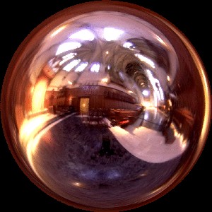
Radiance env map
|
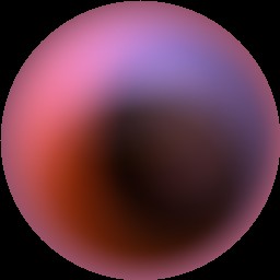
Irradiance env map
|
- Hemispherical integration on each pixel
- Approximation using spherical low pass filtering
Sources


